What is Plasma - It is the the Fourth State of Matter
One common description of plasma is to describe it as the fourth state of matter. We normally think of the three states of matter as solid, liquid and gas. For a common element (water) these three states are ice, liquid water and steam. The difference between these states relates to their energy levels. When we add energy in the form of heat to ice, the ice melts and forms liquid water. When we add more energy, the water vaporizes into hydrogen and oxygen, in the form of steam. By adding more energy to steam these gases become ionized. This ionization process causes the gas to become electrically conductive. This electrically conductive, ionized gas is called plasma
How hot is the plasma arc? = The plasma is then forced through a fine-bore copper nozzle which constricts the arc and the plasma exits the orifice at high velocities (approaching the speed of sound) at a temperature approaching 28,000 °C (50,000 °F) or higher.. Compare this to the surface of the sun which is about 10,000 degrees F.
How Plasma Cuts Through Metal
The plasma cutting process, as used in the cutting of electrically conductive metals, utilizes this electrically conductive gas to transfer energy from an electrical power source through a plasma cutting torch to the material being cut.
The basic plasma arc cutting system consists of a power supply, an arc starting circuit and a torch. These system components provide the electrical energy, ionization capability and process control that is necessary to produce high quality, highly productive cuts on a variety of different materials.
The power supply is a constant current DC power source. The open circuit voltage is typically in the range of 240 to 400 VDC. The output current (amperage) of the power supply determines the speed and cut thickness capability of the system. The main function of the power supply is to provide the correct energy to maintain the plasma arc after ionization.
The arc starting circuit can be Blowback design which is used on the Powermax Series or a high frequency generator circuit that produces an AC voltage of 5,000 to 10,000 volts at approximately 2 megahertz. This voltage is used to create a high intensity arc inside the torch to ionize the gas, thereby producing the plasma.
The Torch serves as the holder for the consumable nozzle and electrode, and provides cooling (either gas or water) to these parts. The nozzle and electrode constrict and maintain the plasma jet.
Sequence of Operating a Plasma Cutter
The power source and arc starter circuit are connected to the torch via interconnecting leads and cables. These leads and cables supply the proper gas flow, electrical current flow and high frequency to the torch to start and maintain the process.
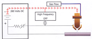
1. A start input signal is sent to the power supply. This simultaneously
activates the open circuit voltage and the gas flow to the torch
(see Figure 2). Open circuit voltage can be measured from the electrode
(-) to the nozzle (+). Notice that the nozzle is connected to positive in
the power supply through a resistor and a relay (pilot arc relay), while
the metal to be cut (work piece) is connected directly to positive. Gas
flows through the nozzle and exits out the orifice. There is no arc at this time as there is no current path for the DC voltage.
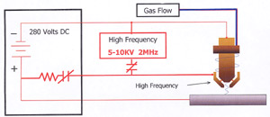
2. After the gas flow stabilizes, the high frequency circuit is activated.
The high frequency breaks down between the electrode and nozzle
inside the torch in such a way that the gas must pass through this arc
before exiting the nozzle. Energy transferred from the high frequency
arc to the gas causes the gas to become ionized, therefore electrically
conductive. This electrically conductive gas creates a current path
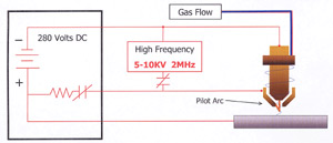
between the electrode and the nozzle, and a resulting plasma arc is formed. The flow of the gas forces this arc through the nozzle orifice, creating a pilot arc.
3. Assuming that the nozzle is within close proximity to the work piece,
the pilot arc will attach to the work piece, as the current path to positive
(at the power supply) is not restricted by a resistance as the positive
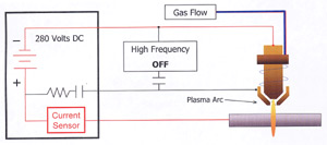
nozzle connection is. Current flow to the work piece is sensed
electronically at the power supply. As this current flow is sensed, the
high frequency is disabled and the pilot arc relay is opened. Gas ionization is maintained with energy from the main DC arc.
4. The temperature of the plasma arc melts the metal, pierces through
the work piece and the high velocity gas flow removes the molten material
from the bottom of the cut kerf. At this time, torch motion is initiated and
the cutting process begins.
Variations of the Plasma Cutting Process - Conventional Plasma Cutting
This process generally uses a single gas (usually air or nitrogen) that both cools and
produces the plasma. Most of these systems are rated at under 100 Amps, for
cutting materials under 5/8" thick. Primarily used in hand held applications
Dual Gas Plasma Cutting
This process utilizes two gases; one for the plasma and one as a shield gas.
The shield gas is used to shield the cut area from atmosphere, producing a
cleaner cut edge. This is probably the most popular variation, as many different
gas combinations can be used to produce the best possible cut quality on a given
material.
Water Shield Plasma Cutting
This is a variation of the dual gas process where water is substituted
for the shield gas. It produces improved nozzle and work piece cooling
along with better cut quality on stainless steel. This process is for
mechanized applications only.
Water Injection Plasma Cutting
This process uses a single gas for plasma and utilizes water either radially or swirl
injected directly into the arc to greatly improve arc constriction, therefore arc density
and temperatures increase. This process is used from 260 to 750 amps for high quality
cutting of many materials and thicknesses.This process is for mechanized applications only.
Precision Plasma Cutting
This process produces superior cut quality on thinner materials,
(less than 1/2") at slower speeds. This improved quality is a result of
using the latest technology to super constrict the arc, dramatically
increasing energy density. The slower speeds are required to allow the
motion device to contour more accurately. This process is for mechanized
applications only.
This information was provided by: