Official Page Launch February 2nd 2018!!!


© 2018-2019 Desert Fabworks LLC - CNC Plasma Info, All Rights Reserved- Trademarks shown on this site belong to their respective owners


CAM Software is the software that takes your CAD drawing or artwork that you want to cut and gets it ready for the machine. CAM - Computer Aided Machining is where were going to set up the cut by telling the machine what were cutting (Aluminum, Steel, Stainless Steel ect.) How thick the material it is and setting up our lead in and outs, cutting amps and speed and host of other data. Most of the settings and operations will be automated to some degree here and can be as simple as picking the material and thickness. Most of the other values will have been set up previously or settings can be imported to match your plasma cutter.
Hypertherm does an excellent job of testing and evaluating materials and machine settings to perfect them. They have all the specifications and settings informational for nearly every material that you would ever cut. There settings are based on ideal circumstances with brand new consumables. The capabilities and design of your table as well as the material that you use can vary slightly so a little tweaking to the settings may be necessary for your application but the cut charts from Hypertherm are a great place to start and have all the info that you need.
There are nearly as many CAM programs available as there are Artwork Programs. For DIY systems, hobby grade and many of the kit form tables Sheetcam brand CAM software is one of the most popular. Many of the higher end and industrial tables come with a proprietary CAM software. Unlike the artwork software the CAM software must be programmed to specifically match up to the table, control system and plasma cutter.
The CAM program is going to take all of the settings you have picked for your material, the thickness, as well as all of the information from your drawing and turn that into something that the machine can use to complete the task and make your object. There are litteraly hundreds of variables that CAM program will control. Each of these vary from program to program but most will automate this very complex process into some thing very simple that can be done with just a few clicks after the program has been populated with all of your machine variables during initial setup. The CAM program usually will create some form of G-Code To accomplish this. G-Code is the language the machine speaks. For more info on G-Code click HERE: The reason CAM software and the G-Code that it generates can not be moved from machine to machine is that these software components have specific information that is unique to your machine and its setup. Trading G-Code files is not recommended the results are most likely not going to work. Instead you can trade or use other peoples .dxf files then process them in your CAM software and export them to your machine. There are many sites available on the Internet where you can get or purchase artwork ready to go like here at: www.cncdxffiles.com
Unique info can include the size and configuration of your steppers or servos, machine table size, plasma cutter and its settings, design of your table, Z axis setup, accessories like air scribes, or rotary devices. Ultimately check with your machines manufacture and the CAM software manufacture to ensure compatibility with your system.
What do we recommend / Use
For our Pro Series plasma table from Westcott Plasma we are using Design2Cut for our CAM program. While this program is proprietary to Westcott Plasma it can be adapted and used with other brands of machine and can be retrofitted to machines using other software options. What is unique with Design2Cut is that it is an all in one solution for your software. Meaning that it can take the place of three programs and allow you to build a CAD part, Complete CAM processing and send it to the Machine for cutting all in one program. This greatly simplifies the task of making something.
In our last machine we would use our CAD program ie, Corel or Drawplus to create the part or artwork we wanted to make. We then saved the file as a .dxf file format. Then we opened a program called Sheetcam and imported our drawing. We processed the part in the CAM software then ran a post processor to turn it into G-Code. Then we opened a program called Mach3 and imported the G-Code file from Sheetcam. Then we ran the cut on the machine. You can see this process was time consuming and if you ran into a problem with a cut you had 3 placed you need to check to find the problem and correct it.
With Design2Cut all of this happens in one place and one program. You can still use other CAD design programs and import the drawings into Design2Cut. Some people may be used to or comfortable with other design software so your not limited in that regard with Design2Cut.
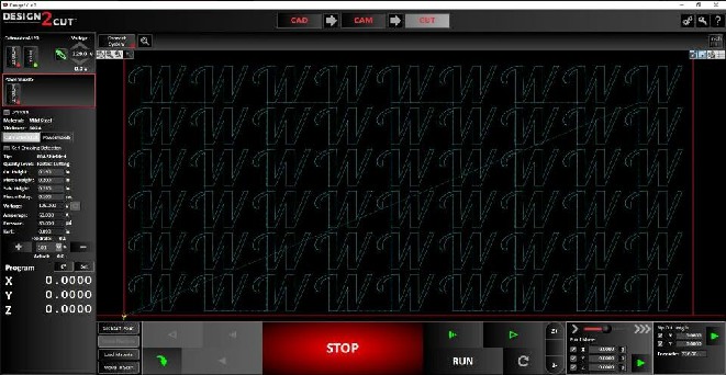
There are some screen shots below from Design2Cut and we will be doing tutorial videos in the Tutorial Section and we will also have some Tips & Tricks.
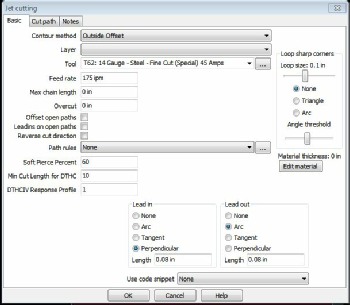
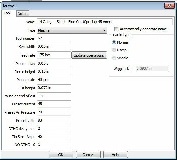
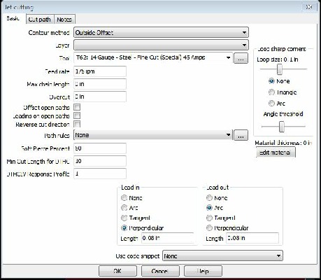
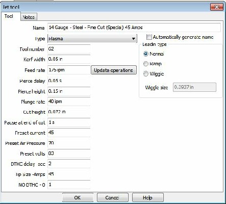
Here are some examples of CAM program settings. These are from sheetcam. The settings and options available will depend on the program that you use. But you can see there are a lot of parameters that can be configured to cut the material.
The second photo shows as (Tool) menu. Each Material can be set up as a tool with of the values and settings you need. Once set you can simply select the material you want and then all the saved values are populated for you.
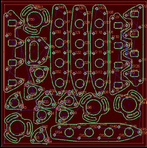
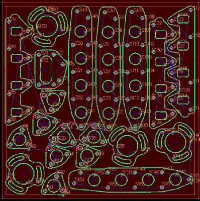
The image to the left is a typical CAM software image. I have taken all of the parts I want to cut and Nested them in a way that allows me to have as little waste as possible. When the plasma torch fires and punches through the material “Pierce” its going to make a bigger hole than the following cut line. This pierce hole is undesirable to have in your finished project so you use Leadins where are a small line that connects to your part. The torch pierces at the start of this small line segment that has been placed on the outside or inside of the object you want to cut so that the finished part does not have pierce in it and the pierce takes place in a waste are of the cut. In the image to the left you you can see the lead ins and outs. Typically the higher the amperage and thicker the material the larger the pierce hole will be and thus the leadin will be larger for thicker vs thin material.
Another component of the CAM software is knowing kerf. Kerf is the width of the cut. Thick of plasma like a circular saw and the thickness of the saw blade as the same as the thickness of the plasma as it cuts through the material. Lower amperage / thinner materials will have smaller kerf than thicker material with high cut amperage.
The cam program automatically places the lead in and outs and adjusts the cut line based on the estimated kerf of the cut. The green line represents where the machine will be on and cutting. The smaller lines are where the torch moves from one start point to another also called a rapid move. All the start points are numbered.